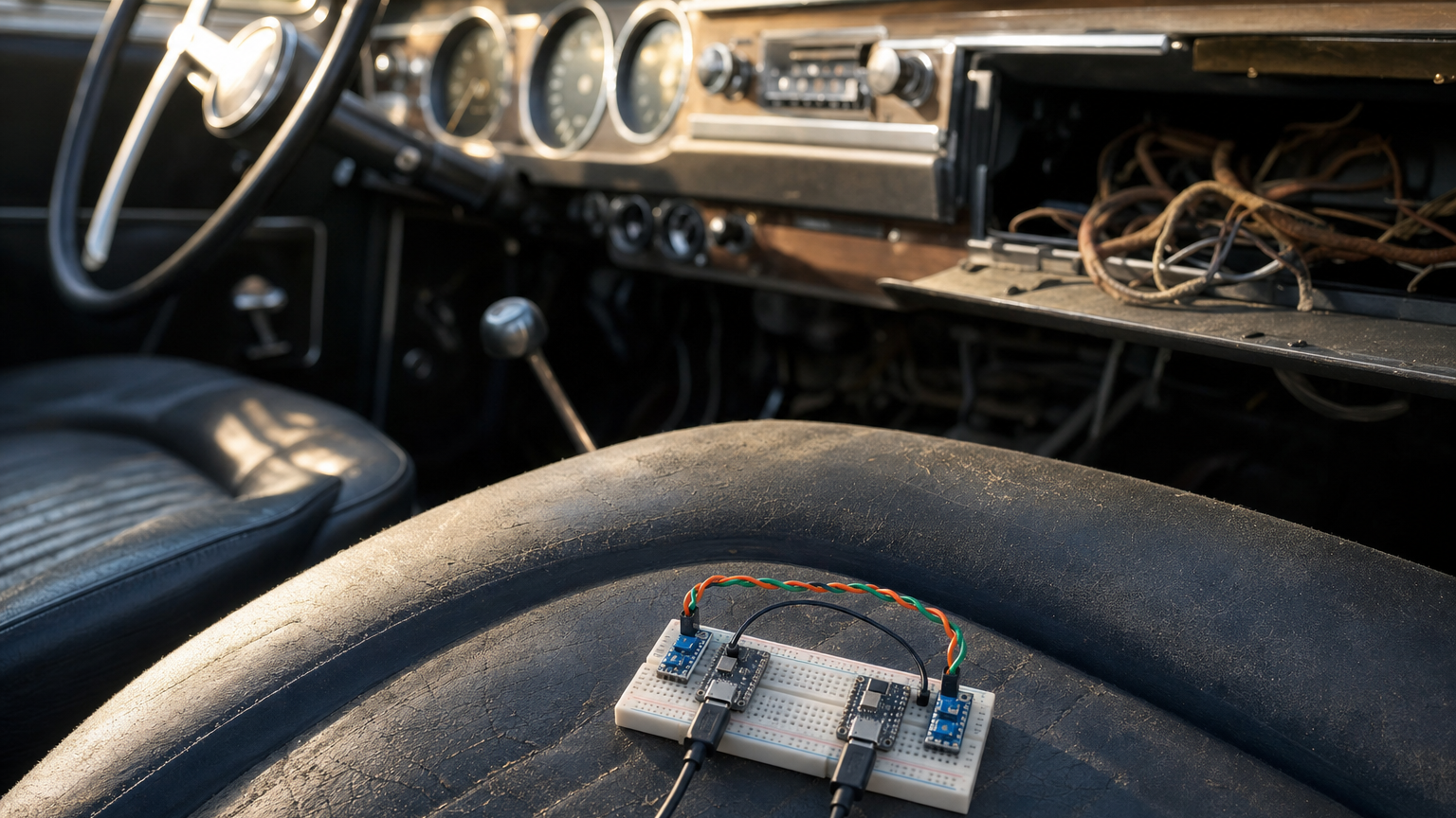
What does a VW Lupo 3L from 1999 have in common with the new Tesla Roadster? Not the range, not the acceleration, and certainly not the price. But if you could listen in on the wires behind the dashboard, you would hear both of them speaking the same language: CAN bus.
In the Lupo 3L, Volkswagen’s own training material describes the gearbox control unit talking to the diesel injection, the ABS and the instrument cluster over a CAN data bus. Tesla’s Model S and Model 3 run several CAN buses behind a central gateway; the community has decoded them in public. Tesla has not published anything about the wiring of the Roadster it unveiled on 15 October, so I am extrapolating here. But I would be genuinely surprised if it broke with the rest of the family.
A protocol that survives nearly 30 years of automotive progress deserves a closer look. Especially if you are about to put it into your own car.
A 1980s design that still has no reason to retire
CAN, short for Controller Area Network, started at Bosch in 1983. Bosch presented it at the SAE congress in Detroit in February 1986, Intel and Philips shipped the first controller chips in 1987, and Mercedes-Benz began using it in its luxury cars in 1991. ISO standardised it as ISO 11898 in 1993. Since then it has been extended with CAN FD (2012) and CAN XL, but classic CAN is still everywhere.
Why? Because the design solves the hard problems of a car’s wiring loom remarkably well:
- Differential signalling. Two wires, CAN_H and CAN_L, carry the signal as a voltage difference. Interference from an ignition coil hits both wires equally and cancels out.
- No master. Any node can talk. If two start at once, bitwise arbitration decides: the frame with the lowest identifier wins, and the loser simply backs off and retries. Nothing gets destroyed, and nobody needs to coordinate.
- Built-in error handling. Every frame carries a 15-bit CRC and needs an acknowledgement. Each node keeps transmit and receive error counters, and a node that misbehaves too often switches itself off (bus-off) instead of dragging everyone else down.
That last point is my favourite. A broken sensor does not take your whole car with it. It quietly removes itself from the conversation.
Why I want CAN in a car from the 1970s
You may know my Peugeot 304. The S version with its twin-carburettor engine arrived in 1972, a time when “vehicle electronics” meant a fuse box and a hopeful attitude.
I do not want to retrofit a few gadgets. I want to rebuild the electrics myself: ESP32 boards with sensors, scattered around the car, all talking to each other over CAN. The brain in the middle will be a Raspberry Pi 5. One thing to know if you are planning something similar: the Pi has no CAN controller of its own, so it needs a CAN HAT and SocketCAN on the Linux side.
Before I drill a single hole into a 50-year-old body, though, I wanted to understand the bus properly. Not from a datasheet, but on my own desk.
CAN-Lab: two boards, two wires, one browser tab
So I built CAN-Lab. Not entirely on my own, admittedly, but I am rather proud of how it turned out. The code is open source under GPL-3.0 on GitHub, and the repository contains the finished sketches.
The hardware is deliberately cheap: two ESP32-C3 SuperMini* boards, which have a CAN controller built in (Espressif calls it TWAI), and two SN65HVD230 transceiver modules*, which turn the logic signals into bus levels. Add a breadboard, a few jumper wires and two USB cables, and that is the entire lab.
CAN-Lab itself runs in Chrome or Edge. It uses the Web Serial API, which I wrote about a while ago, to read both boards at once, so nothing leaves your machine.
This project is aimed at IoT enthusiasts who have flashed an ESP32 before. If PlatformIO and a breadboard do not scare you, you will have it running in an evening.
Load testing a bus that is older than some of my colleagues
The connection check sends one frame per second and shows you whether frames arrive and whether any go missing. Useful, but a little boring.
The fun part is the load test. You pick a target rate and a duration, CAN-Lab arms both boards, and then it plots frames queued against frames received, along with the error counters, in real time.
On my setup I reached 4,303 frames per second without losing a single message: no counter gaps, no bus errors.
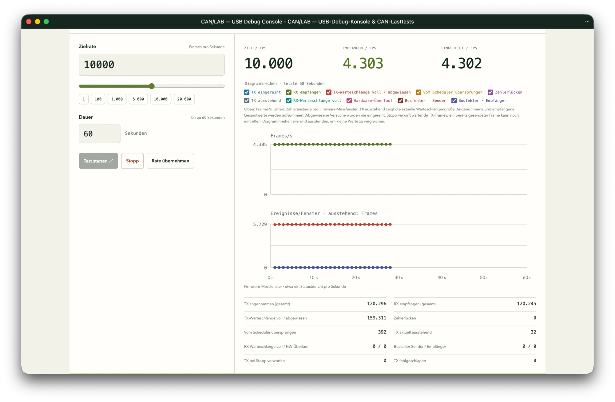
I offered 10,000 frames per second on purpose. The sender’s queue rejected everything the bus could not carry, and what did get through arrived complete and in order. That number made me sit up, because it is close to the physical limit. At 500 kbit/s, a classic frame with 8 data bytes needs 111 bits including the gap between frames, and up to 135 bits once bit stuffing kicks in. That gives you a ceiling somewhere between roughly 3,700 and 4,500 frames per second. In other words, two boards that cost a few euros each were filling the wire, not giving up on it.
For my Peugeot this means bandwidth is the last thing I need to worry about. A handful of temperature, pressure and speed sensors will barely register.
Try it yourself
Everything you need to rebuild the test is in the CAN-Lab white paper, free to download below: parts list, wiring diagrams, flashing, the load test step by step and a troubleshooting section, plus the full results and the measurement method. I am curious whether you beat my 4,303 frames per second, and what you plan to put on the bus once you trust it.
Links marked * are affiliate links. As an Amazon Associate I earn from qualifying purchases. The price stays the same for you.